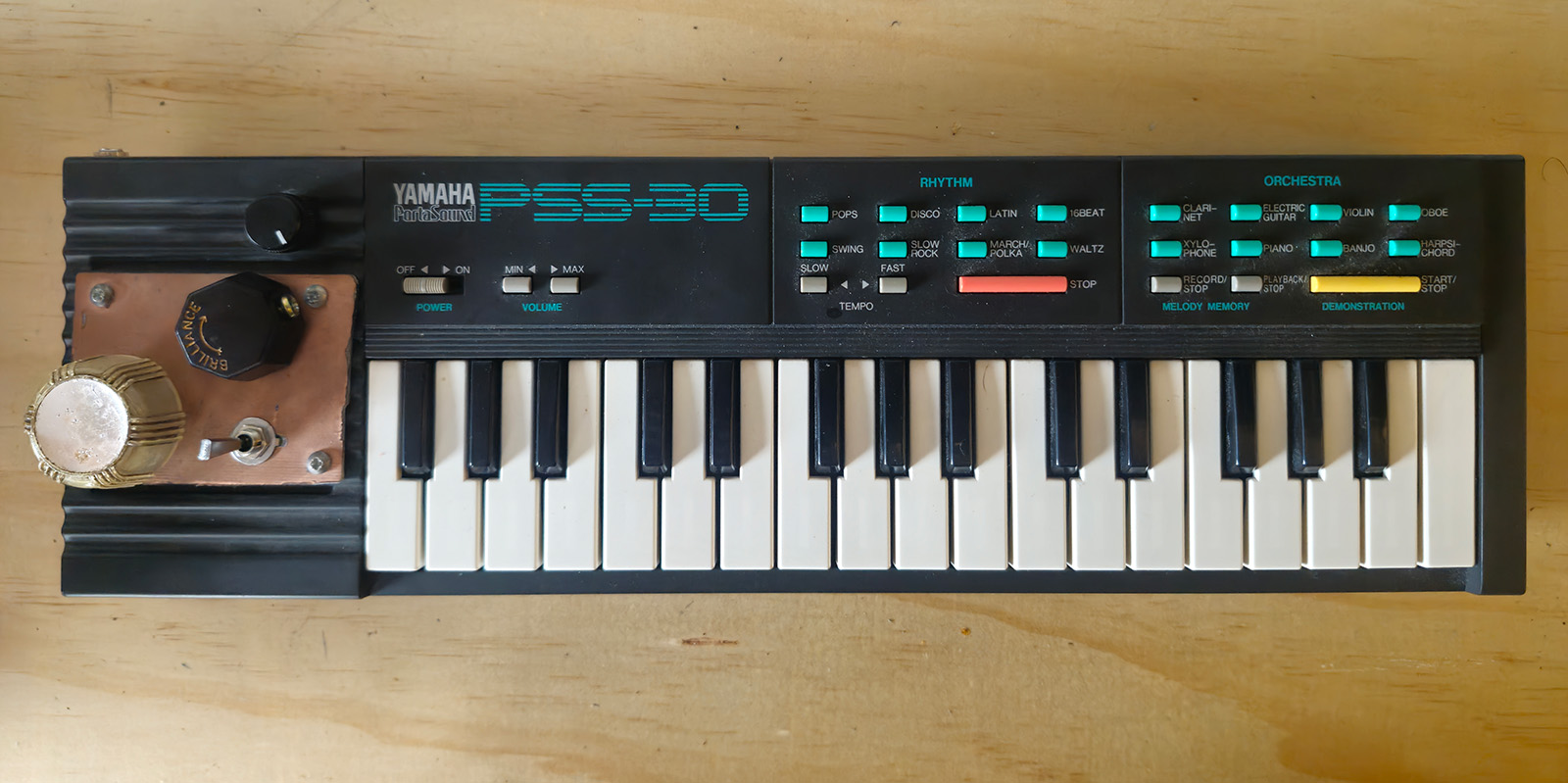
This was a circuit-bending project involving modifications to a Yamaha PSS-30. The modifications include improved volume adjustability in the form of a knob (the original volume control is stepped because its adjusted with up and down buttons), an audio-out jack, a knob for adding overdrive, a knob that adjusts clock speed, and a switch which augments what the clock speed control is able to do, which is explained below.
When researching other Yamaha PSS-30 projects, there seemed to be a common belief that this keyboard (as well as its nearly-identical counterparts, the PSS-1301 and PSS-1202) is virtually impossible to get interesting sounds out of through circuit-bending1, 2, 3, 4, 5, 6. At the center of this view is a sense of disappointment that the CPU IC (Yamaha YM2410) isn't more receptive to circuit-bending. Some have pointed out that the datasheets for the YM2410 has not yet been scanned, and therefore the exact pinnout of the IC is not fully known. However, a supposed replacement chip, the YM24137 is listed online with a datasheet8, and the pinout for the YM2410 has been speculated on through analysis1. There is also a service manual for the PSS-130 keyboard9, but it unfortunately doesn't have any pinout info for the YM2410.
In spite of this perception, many people have circuit-bent PSS-30s with inventive modifications. The different approaches to modification can be organised in the categories of 1.) modifications with the amplifier IC (LM386), 2.) modifications with the YM2410, 3.) auxilliary effects circuits, and 4.) other simple modifications.
1.) Modifications to the amplifier IC (LM386)
~Overdrive added by decreasing the resistance set with the resistor next to the LM386. Replacing the resistor with a potentiometer allows for the amount of overdrive to be adjustable10, 11, 12, 13.
~Adding filters like high pass and low pass filters, and bass boosting circuits10, 11, 12, 13, 14, 15.
~Creating an oscillator with the LM386 by feeding it back on itself.
2.) Modifications with the YM2410
~Clock speed modifications by replacing the crystal oscillator with something else, like an LTC1799.
~Splitting effects/signal mixing of the rhythm sounds and the pitch-organised sounds
3.) Auxilliary effects circuits
~Other circuits added for features such as sequencers
4.) Other Simple Modifications
~Audio out jack added
~Potentiometer for continuous volume adjustment
Some very inventive projects use auxiliary effects circuits, while others take simpler approaches that, especially when combined, can still produce surprisingly creative results8, 9. In this project, clock speed modification (although one of the most basic circuit-bending techniques) was explored as a primary method for generating unexpected sounds.
The keyboard proved capable of handling extreme low speeds (down to individual clicks) and extreme highs (up to piercing whistle tones), but what became most notable were the ranges beyond those limits. In these outer zones, chaotic and unpredictable sounds, textures, and rhythms began to emerge — elements that appeared less prominently in many of the other modifications reviewed. In this project, the focus on pushing into these extremes was not based on an especially novel approach, but rather on extending a simple technique into less commonly explored territory.
The PSS-30 uses a crystal oscillator that sets the clock speed at 607 kHz1. Many devices rely on crystal oscillators for timing, and adjusting the clock speed in these cases requires an adjustable oscillator, such as the LTC179910. In this project, an LTC1799 module from circuitbenders.co.uk11 was used, as direct work with surface-mount components was avoided at this stage to simplify assembly and testing.
Multiple potentiometer values were tested to determine the maximum and minimum resistance limits that the keyboard could tolerate before cutting out or going silent. To explore the extreme low range, one lug of the main potentiometer was connected toward ground. Direct grounding caused the circuit to cut out, so a secondary potentiometer was added between the lug and ground to gradually reintroduce resistance. This allowed incremental adjustments until sound returned. The resistance value on the secondary potentiometer at that point was measured with a multimeter and then replaced with fixed resistors to create a stable circuit. This method extended the limits of the main potentiometer in a controlled way and does not appear to have been documented in other PSS-30 circuit-bending projects.
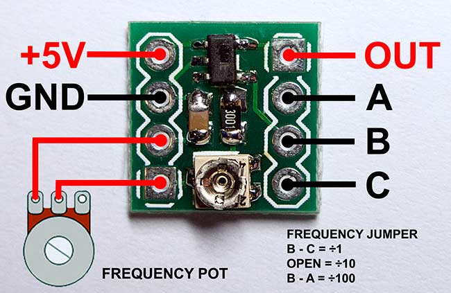
The resultant circuit is shown below. The generic LTC1799 module pinout/hookup diagram can be found on the circuitbenders.co.uk website for reference12. Also note that "CLK O" refers to "Clock Out".

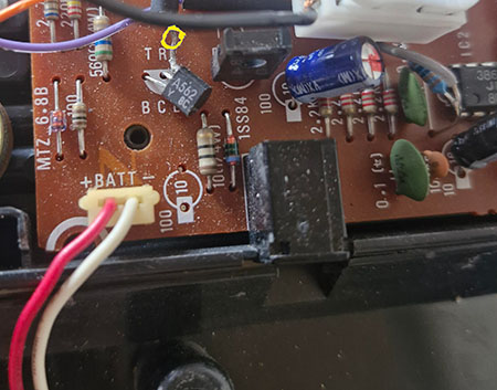
The +5V supply is taken from the emitter of one of the board's transistors (labelled TR2 on the board). This is a delicate connection, as the emitter must remain soldered in place while a wire is attached directly to the side of the leg. See image below:
The LTC1799 was installed in an IC socket to allow for easy replacement in the event that the module burned out. This assembly was mounted on a piece of scrap stripboard along with the required resistors, and the stripboard was then fixed to the back of the main PSS-30 board using electrical tape. While this method proved more secure than it might appear once the unit was reassembled, it is not an ideal long-term solution.
A more robust mounting approach would involve replacing one of the screws securing the main PSS-30 board with a longer equivalent, allowing the stripboard to be fastened in place. Plastic washers could be used as spacers to elevate the stripboard, accommodating its uneven surface and preventing it from being compressed or damaged against the underside of the main board.
Version 2
After several months, the LTC1799 module failed and required replacement. By this stage, a more cost-effective approach had been adopted, involving LTC1799 chips mounted directly onto 5-pin SMD-to-DIP adapters, and a small stock of these had been prepared. With no remaining LTC1799 modules from circuitbenders.co.uk, the clock modification circuit required redesign, as the DIP-adapted LTC1799 differs in its connections from the pre-assembled modules, which include onboard capacitors and trim potentiometers.
Although this necessitated revisiting the circuit design, it also provided an opportunity to refine the approach. An additional outcome was the development of two alternative circuit designs, allowing for either implementation to be used or shared.
The diagram below outlines the second circuit design for a standard LTC1799:

When adapting the original circuit design to use a DIP-converted LTC1799 in place of the circuitbenders.co.uk module, the aim was simply to restore the behavior of the previous modification. Testing revealed that the circuit's response depended on how the right lug of the potentiometer was connected. Through the resistor network, the familiar extreme low range was accessed, producing slow, unpredictable sounds. Connecting directly to ground unlocked a high-range zone, generating chaotic rhythms and unusual textures. A DPST switch was added to toggle between these configurations, providing access to both unique sonic ranges without altering the rest of the circuit. Outside of those extreme ranges this switch also lets you toggle the pitch of the keyboard up or down by about a minor 3rd, which can create some interesting performance possibilities when the keyboard is being played, the switch is being toggled, and the clock speed pot is being adjusted all at the same time.
The clock speed modification works by replacing the PSS-30's original crystal oscillator with an LTC1799, allowing the oscillation frequency to be adjusted via a potentiometer. The voltage at the LTC1799's SET pin directly determines the clock speed, and the potentiometer in combination with the surrounding resistor network acts as a voltage divider, controlling this voltage. Turning the wiper changes the voltage at the left lug, which in turn alters the SET voltage and the resulting oscillation frequency. The extreme ranges of the keyboard emerge when the circuit is pushed beyond its typical linear operating range: connecting the right lug through the resistor network accesses the familiar slow, chaotic low speeds, while connecting it directly to ground forces the voltage divider into a different configuration, creating a high-speed zone with unusual rhythms and textures. In both cases, the keyboard is effectively being driven to act non-linearly, revealing sonic behaviors that are otherwise inaccessible with standard clock speeds.
Reflection
What I find most compelling about these non-linear zones is how quintessentially circuit-bent they feel. They are, in a sense, the "hidden voice" of the PSS-30 — operating far beyond the smooth, linear behavior of the unmodified keyboard. Through circuit-bending, these zones aren't artificially imposed; they are revealed. My approach to any circuit-bending project is shaped by a philosophy that values listening, responsiveness, and attention to emergent behaviors. Coming into this project with that perspective guided what to listen for and how to design toward building a relationship with this particular device.
In my view, circuit-bending is not about coercion or forcing the device into unconventional states. It is about fostering conditions where the instrument can express itself and collaborate. The noises, textures, and unexpected rhythms that emerge are part of the PSS-30's language — non-verbal, inherently expressive, and alive.
References
1 Christian Oliver Windler. Yamaha PSS-30, PSS-130 (small squarewave keyboard with unusual percussion) Warranty Void, c. 2007 (archived).
http://weltenschule.de/TableHooters/Yamaha_PSS-30.html
Provides a detailed breakdown of the PSS-30, including analysis of its design and history. The site itself serves as a valuable archive of instruments commonly used in circuit-bending.
2 alex. Analog Relics. Yamaha PSS-120 / PSS-130 Circuit Bending. circuit-bent.net, January 9, 2020.
https://circuit-bent.net/yamaha-pss/analog-relics-yamaha-pss-120-pss-130.html
Write up including documenting the PSS-120, and provides descriptions of the PSS-120 and PSS-130.
3 hippyjon, Orangery, and boneless. yamaha pss 30. circuitbenders.co.uk forum, November 23, 2006 – May 17, 2011.
https://www.circuitbenders.co.uk/forum/index.php?topic=268.0
Community discussion of PSS-30 circuit-bending experiments. Documents shared observations about the instrument’s behavior and perceived limitations.
4 Forrest Galvin. UH YEAR. NOYSTOISE, January 16, 2012.
https://www.noystoise.com/2012/01/uh-year.html
A detailed project write-up documenting an extensive modification of a Yamaha PSS-30 keyboard. Includes significant added circuitry such as a sequencer, filters, CV integration, and a complete rebuild in a new chassis, demonstrating a highly expanded approach to circuit-bending.
5 darklife. Circuit Bent, or synth?.. Yamaha PSS-130. Electro-Music.com Forum, May 20, 2018.
https://electro-music.com/forum/topic-69989.html
A forum post detailing a PSS-130 circuit-bending project with a step sequencer modification. Includes build photos and schematic drawings, illustrating inventive approaches to expanding the functionality of the keyboard.
6 kagemichaels. My overkill circuit bent Yamaha PSS-130. Reddit (r/CircuitBending), c. 2016–2017
https://www.reddit.com/r/CircuitBending/comments/8jz5df/my_overkill_circuit_bent_yamaha_pss130/
Detailed PSS-130 circuit-bending project; overlaps content with Electro-Music forum post (5) by the same author (there using the username "darklife").
7 explodedsun, OneEyedPlankton, and DevanWolf. I'm having trouble finding a datasheet for IC YM2410. Reddit (r/AskElectronics), January 9, 2013.
https://www.reddit.com/r/AskElectronics/comments/1ccpm0/im_having_trouble_finding_a_datasheet_for_ic/
Community discussion about locating YM2410 datasheet information.
8 Yamaha Corporation. YM2413 Datasheet. n.d.
https://www.waveguide.se/?article=46&file=ym2413ds.pdf
Datasheet for YM2413, a possible YM2410 replacement.
9 Yamaha Corporation. Yamaha PSS-130 Service Manual. n.d.
https://static.wikitide.net/circuitbendingwiki/d/d4/Yamaha_PSS-130_Service_Manual.pdf
Official PSS-130 service manual; lacks YM2410 pinout info.
10 Sam Vs. Sound. LM386 Modifications – Yamaha PSS-30 May 10, 2017.
https://static.wikitide.net/circuitbendingwiki/d/d4/Yamaha_PSS-130_Service_Manual.pdf
Guide to LM386-based modifications including overdrive and bass boost.
11 Soundquist. Circuit Bent PSS-130. MATRIXSYNTH, July 23, 2014.
https://www.matrixsynth.com/2014/07/circuit-bent-pss-130-by-soundquist.html
Listing and images for a circuit-bent PSS-130.
12 Squidfanny. Circuit Bent YAMAHA PSS-30. MATRIXSYNTH, May 11, 2010.
https://www.matrixsynth.com/2010/05/squidfanny-circuit-bent-yamaha-pss-30.html
Listing and images for a circuit-bent PSS-30.
13 mad_marbled et al. The Yamaha PSS-30 my 1st successfully bent keyboard. Reddit (r/CircuitBending), October 2016.
https://www.reddit.com/r/CircuitBending/comments/7cm0vh/the_yamaha_pss30_my_1st_successfully_bent_keyboard/
Discussion of multiple PSS-30 bending projects.
14 Sam Vs. Sound. Tone Control and Line Out – Yamaha PSS-30.May 24, 2017.
https://samvssound.com/2017/05/04/tone-control-line-yamaha-pss-30/
Guide on tone control modifications for PSS-30.
15 darklifeimages. Yamaha PSS-130 Circuit Bend / Synth. Imgur, May 17, 2017.
https://imgur.com/a/yamaha-pss-130-circuit-bend-synth-by-kage-2018-UXI61hZ
Album of photos showing a PSS-130 circuit-bending project including schematics. Same author and project as (5),(6).
